High spectral efficiency is crucial in enabling cellular and other radio networks to deliver sufficient capacity, high data rates, good coverage, and high quality-of-service. Improvements to spectral efficiency can also be used to significantly reduce infrastructure equipment and operational power consumption, with less equipment needed to provide the same network performance.
AccelerComm® provides complete physical layer IP solutions and components which enable optimal performance of 5G radio access networks and solve the challenges that would otherwise limit the throughput, latency, and spectral efficiency of 5G, by mitigating the effects of noise, interference and poor signal strength.
A challenge that we have faced both externally and internally is: How do we quantify the spectral efficiency improvement from the advanced algorithms provided by AccelerComm® to our customers, so that every stakeholder in the value chain can instantly understand the value of the benefit. With this series of posts, we have set out to explain how we overcame this challenge. And in this very first post, we introduce a key simulation tool built by AccelerComm® that quantifies the spectral efficiency and demonstrates the benefit with ease. We call this the PUSCH Channel Simulator.
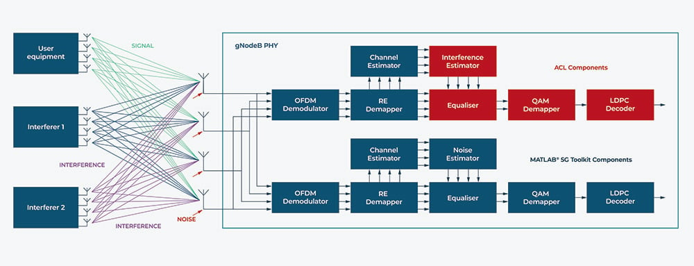
A 5G base station (gNodeB) comprises Radio Unit (RU), Distributed Unit (DU) and Control Unit (CU). The focus of our PUSCH Channel Simulator is the high PHY of the DU. It simulates the throughput (i.e. data rate) versus received signal quality with interference (i.e. SINR, Signal to Interference and Noise Ratio) for Physical Uplink Shared Channel (PUSCH) in a MATLAB® environment. Importantly, this simulator mimics the entire transmit and receive process, from generating the message in the user equipment, transmitted via a channel model, adding quantified interferers to the signal and then receiving it through the PUSCH processing chain in the gNodeB. As an output, it generates a graph which shows the Throughput vs SINR, where 100% throughput at a particular dB represents the messages get sent in the first transmission with no need for any Hybrid Automatic Repeat Request (HARQ) retransmission, whereas 0% means no messages are sent after four retransmissions.
To perform 5G 3GPP-compliant signal processing on the message, the PUSCH chain comprises some of the key processing components of the DU, namely OFDM demodulator, RE demapper, channel estimator, noise/interference estimator, channel equaliser, QAM demapper and LDPC decoder. To quantify the performance of AccelerComm® IP solution and provide a like-for-like comparison, two signal processing chains are modelled alongside each other in the simulator, as shown below. More specifically, the primary chain comprises all the components from MATLAB® and 5G Toolbox, but with interference estimator, channel equaliser, QAM demapper and LDPC decoder from AccelerComm®; whereas for the benchmarking chain, all components are from MATLAB® and 5G Toolbox. Moreover, each component can be swapped in and out with alternative solutions, so the impact of these components can be observed individually on the PUSCH Channel of the high PHY.

In this way, the PUSCH Channel Simulator has enabled AccelerComm’s own engineers and its customers to comprehensively analyze the detailed behaviour of the PUSCH processing components, thereby demonstrating the spectral efficiency gains achieved by our IP solution.
If you are interested in our PUSCH channel end-to-end simulator, please register your interest here.
To find out more about AccelerComm®
- Download our company presentation
- Read more about our PUSCH Equalizer
- Get in touch to speak to our experts directly
